


Proyecto APHRES
Principio Arcusín sobre hidrodinámica de roto-traslación para ahorro de energía
Arcusin principle on hydrodynamic of roto-translation for energy saving
Open Report
Detailed results for 1 and 2 cylinders proving ARCUSIN principles
July, 2022
Authors: Carlos Arcusín (Promoter); Mariano Pérez Sobrino (Developer); Héctor Díaz Ojeda (CFD Manager)
ÍNDICE / INDEX
- List of Symbols.
- Introduction and historical review.
- Results at model scale.
2.1. One cylinder case. ARCUSÍN Principle number 1.
2.1.1. Test number 1 results.
2.1.2. CFD results and comparison.
2.1.3. Physical analysis.
2.1.4. Non-dimensional analysis.
2.1.5. Results with over-rotation.
2.2. Two cylinders case. ARCUSIN Principle number 2.
2.2.1. Model tests results.
2.2.2. CFD results and comparison.
2.3. Validation with new program of model tests.
2.3.1. One cylinder tests.
2.3.2. Two cylinders tests.
2.4. Conclusions at model scale. - CFD results at different scales.
3.1. Cylinder geometry.
3.2. Two cylinders cases.
3.2.1. Selected cases.
3.2.2. Non-dimensional analysis. - Final Statements.
- Lines of future applications of the ARCUSIN Principles.
- References.
0. List of Symbols
Most of the symbols used have been defined in the text itself, but in any case the main symbols that appear are listed below:


1. Introduction and historical review
The object of the APHRES Project is to investigate about the effects of rotating cylinders; the project started in the earlies 1980’s when some model tests were carried out in the towing tank of the University of Buenos Aires (U.B.A.), Argentine.
At the end of the 1980s, contact was made with «Canal de Experiencias Hidrodinámicas de El Pardo», which is a center of recognized prestige for hydrodynamic experimentation, located in El Pardo (near Madrid, Spain), and preliminary tests were carried out placing a cylinder in the bow of a barge and other studies that could not be completed due to lack of financial support. The results were encouraging but not definitive.
More recently a wide set of CFD (Computer Fluid Dynamics) calculations using Open-Foam code has been performed. The objective was to demonstrate the certainty of the following principles:
ARCUSIN principle number 1:
A body of revolution that moves through the water-air interface, submerged at 30% of its diameter, rotating at the so called “rotational synchronized speed” with the forward speed, produces not only that the friction resistance practically disappears but also the pressure resistance dramatically decreases with respect to the resistance of the no rotating cylinder.
The so called rotational synchronized speed is the speed of rotation needed to get that the tangential speed of the cylinder surface be equal to the advance speed of the cylinder.
ARCUSIN principle number 2 – Interaction of bodies of revolution (cylinders):
When two or more bodies of revolution advance through and rotate at the synchronized rotation speed, partially submerged in the water-air interface, at a minimum distance of 5% of its diameter, the cylinder that goes upstream, not only has no resistance to advance but develops a thrust force that decreases as the separation or distance with the following cylinder increases.
During the development of this extensive calculation program at the end of 2019, the DNVGL Classification Society was requested to provide a technical review service for part of these calculations, specifically the calculations with one and two cylinders that demonstrated the two principles. The technical review concluded that the validity of the two exposed principles was confirmed.
Finally, during 2021 a new test program has been carried out, resuming contact with El Pardo facilities, this center currently is called INTACEHIPAR, with the aim of obtaining also an experimental confirmation of these principles. The necessary tests with one and two cylinders have been strictly carried out, by means of a specifically designed test device, to verify the validity of the principles in small-scale physical tests, as originally done. The plan is to apply this device to the dynamic study of the behavior of a possible generator of renewable energy based on the second principle of ARCUSÍN. This second part of the test plan with physical models is pending obtaining the necessary funds.
All these calculations and relevant results for demonstrating the validity of the ARCUSÍN Principles are presented in the successive sections of this report. The physical model tests, both the original ones and the most recent ones, have been carried out with cylinder models with a diameter of less than 1m and are presented in section 2. However, through CFD calculations, cases of two cylinders at different scales have also been addressed and they are presented in section 3. In section 4 a final statement on the validity of these principles is affirmed and section 5 presents some possible applications foreseen as future technological developments pending obtaining the corresponding financing.
Although there is no shortage of works and studies on the behavior of different aspects of cylinders subjected to an incident flow, no specific works have been found on our problem. Reichl et al (2005) can be considered one of the first numerical works that studies the influence of the free surface in a 2D cylinder numerically. He does it with Ansys, taking into account the vorticities. Bouscasse et al (2017) is another work that studies the effect of the free surface numerically but with another methodology, SPH. It does so for a Re 200. Miyata et al (1990) is a classic that experimentally studies the effect of depth on a cylinder. Rahul Subburaj (2019) numerically studies the tandem arrangement of two cylinders near the free surface. The works of Bernitsas et al (2008 and 2009) on the VIVACE project deal with the possibilities of extracting energy through the oscillation of the flow in the cylinders. Williamson (1996) is another classic that does a comprehensive review of cylinder fluid dynamics.
2. Results at model scale
In the following the results of the initial set of model tests which was carried out in the towing tank of the “Universidad de Buenos Aires” are presented.
2.1. One cylinder case. ARCUSIN Principle number 1.
Test number 1 consisted in the measurement of the total resistance of a cylinder partially submerged moving forward in transversal position at different speeds, in two conditions: WITOUT rotation and WITH rotation. Main data are presented in next table:
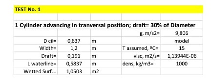
2.1.1. Test number 1 results
The cylinder was mounted in a shaft on a support frame to be towed as in a standard resistance test:
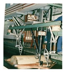
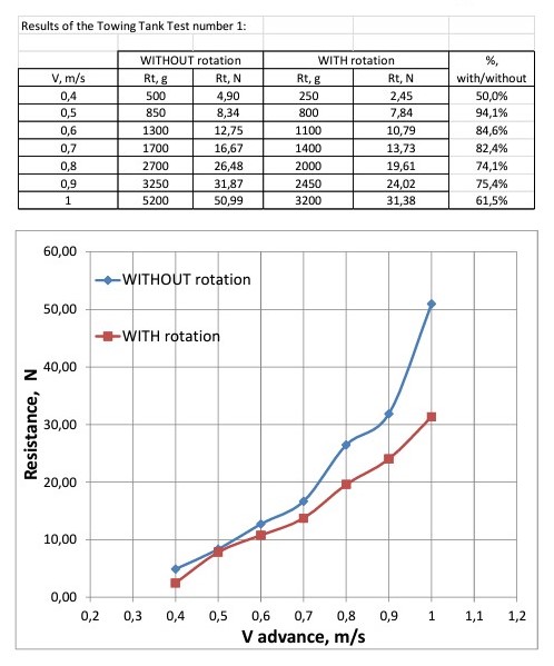
The speed of rotation was not measured during the tests; simply the cylinder rotates due to the friction with water, when the rotational speed was stabilized the resistance was measured.
In spite of the simplicity of these tests it was very clear that a resistance reduction was achieved.
2.1.2. CFD results and comparison
Recently with the launching of the APHRES Project, CFD calculations using OpenFoam code has been carried out to investigate more deeply in these hydrodynamic phenomena.
CFD Codeused: OPEN-FOAM
Volume domain defined:
This picture shows the domain that was defined to make flow calculations. The symmetry condition has been used to divide the domain longitudinally.
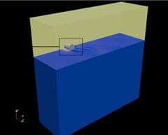
The main purpose was, in these initial calculations, to reproduce the Test number 1 and check its results.

In the cases WITH rotation, the speed of rotation was simulated by imposing at flow a boundary condition in the cylinder surface consisting in a tangential speed equals to the advance speed of the cylinder.
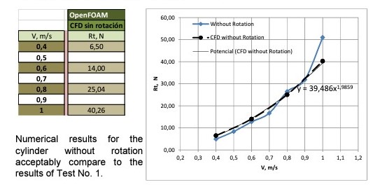
Numerical calculations WITHOUT ROTATION
Numerical Calculations WITH ROTATION:
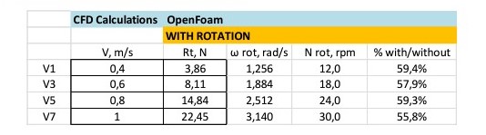
There are some differences between the numerical results for the cylinder WITH rotation when compared to the results of Test Number 1. The reason is that during the tank test the rotation speed was not controlled.

It can be deduced that: Resistance WITH rotation becomes between 55% and 60% of the Resistance WITHOUT rotation.
2.1.3. Physical analysis.
In theory, the resistance of a floating body advancing in the surface of water depends only on its shape, displacement and speed of advance. For this reason, apparently, it should not be affected by rotation.
The total resistance is theoretically divided in two major components: frictional resistance and pressure resistance which is responsible of the generation of the wave pattern. It can be assumed that rotation decreases the friction component practically to zero, because the relative speed between the surface of the cylinder and the flow of water is null. In this case, the viscous resistance has been calculated and it was lower than 12% of the total resistance. But the reduction of the total resistance has been much higher than that.
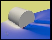
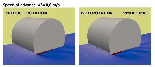
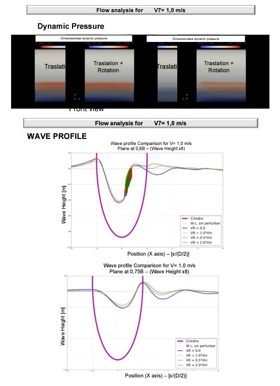
The comprehension of this physical phenomenon needs the analysis of the type of flow developed around the cylinder without rotation and how it changes when rotation is applied to it. Next pictures show different aspects of the flow WITH and WITHOUT rotation at maximum speed tested:
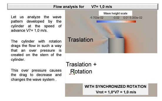
The effect of the height of the flow produced by the cylinder rotation can be shown in the view from the stern of the rotating cylinder.
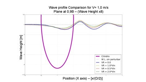
In previous pictures the wave heights have been over-scaled.
It has been proven that the cylinder rotation does not only decrease the friction component, and therefore the viscous resistance, but also changes the wave pattern next to the cylinder, thus creating a crest in the stern that reduces the wave making component of resistance.
Although it is difficult to compare the case of a beam cylinder with that of a conventional ship, what seems to happen is that the interaction between the viscous phenomena and those of wave making, which are usually included in the so-called pressure resistance of viscous origin, is very important. In a conventional ship, the viscosity produces the appearance of the boundary layer and its separation from the hull in the stern area of the ship causes the pressure distribution on the hull and therefore the wave system to change, generally causing to increase the total resistance. In the non-dimensional analysis of the components of the resistance that is used for the extrapolation of the results of the tests with models to the scale of the real ship, this part of the resistance is incorporated into the viscous resistance through the so-called form factor (1+k) which also includes other phenomena: Cv= (1+k) . Cf.
2.1.4. Non-dimensional analysis.
In the non-dimensional analysis of the advance resistance and its components, the following coefficients are used, making these forces dimensionless with the value of the dynamic force ½·ρ·S·V2.
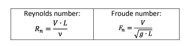
The reference parameters used are the Reynolds number and the Froude number:
And the dimensionless forces coefficients result:
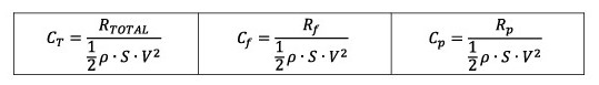
In conventional analysis it is assumed that the friction coefficient Cf, or the viscous coefficient, Cv, depend primarily on the Reynolds number, Rn, while the coefficient of pressure forces, Cp, or that of wave making resistance, Cw, depend mainly on the Froude number, Fn. The expressions that are established and that allow extrapolating the results obtained at the scale of a model to the size of the full ship are:
CTm= Cvm + Cwm, and therefore: Cwm= CTm – Cvm
Since the test is carried out at the same Froude number as the real ship, it can be assumed that Cvm= Cvs= Cv, where the suffix “m” means model and the suffix “s” means ship. The CTm value is measured in the test and the Cvm value is calculated using the expressions:
Cvm= (1+k) . Cfm being: Cfm= 0.075 / (log Rnm – 2)2
Finally, total resistance of the ship would become:
CTs= Cvs + Cw= (1+k) . Cfs + Cw
It is assumed that there is no effect of scale in the form factor, which is calculated by the Prohaska method or other methods. The formula for Cf is the same for the model or the ship but using the corresponding value of Rn in each case.
To apply this analysis to the CFD calculations made with a cylinder WITHOUT and WITH rotation, only in the part corresponding to the model size, it is going to be assumed that the form factor has a value of (1+k)= 1.5, and that the frictional resistance in the case of the cylinder with synchronized rotation is zero, leaving:
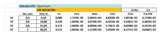
And WITH rotation:
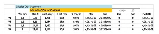
That means that the coefficient of resistance due to wave making, Cw, which somehow represents the energy of the wave system generated by the cylinder, is much lower in the case of advance WITH rotation:
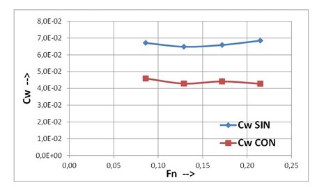
Another way of understanding it is that the rotation of the cylinder causes the socalled Pressure Viscous Resistance to decrease greatly, compared to its value in the case of NO rotation, decreasing the total resistance of the cylinder in its advance.
2.1.5. Results with over-rotation.
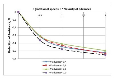
To complete the analysis of the influence of the rotation of 1 cylinder there has been calculated some extra cases, for the same speeds of advance, with different rotational speeds. This picture shows the results in terms of the reduction of resistance achieved.
Therefore, it can be said that all these results obtained with 1 cylinder represent a confirmation of the ARCUSIN Principle number 1 as defined in the introduction of this report.
2.2. Two cylinders case. ARCUSIN Principle number 2.
Trying to find a way to study the interaction of bodies in roto-traslatory movement under different conditions, a 2-cylinder system was built to allow the change of the distance between them, to block and unblock the cylinders independently one from the others and to easily modify the draft, so as to see how the principle behaves in this case.
2.2.1. Model tests results
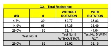
These were the original configuration and the results of the so-called Test number 5 with 2 cylinders:

Next table shows the results obtained in the towing tank in four configurations depending on what cylinder was rotating or not. In any case the speed of rotation of the cylinders was not controlled during these preliminary model tests.

2.2.2. CFD results and comparison
Although a large amount of cases have been simulated and calculated with OpenFoam code, in order to confirm the validity of the ARCUSIN Principle number 2 as defined in the introduction of this report, calculations corresponding to maximum speed of 1 m/s and with both cylinders rotating (configuration D) will be presented here to analyse the following aspects:
- The influence of the separation of cylinders, and
- Different speeds of rotation
Next picture shows the effects in the wave pattern generated by the system with different separations:

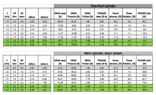
The resistance (in N) of each cylinder with different separations are presented in the following tables:
Comparison of CFD results and model tests are not very much accurate in the case of 2 cylinders, but it must be taken into consideration that several years ago these preliminary model tests were performed in a simple way with no control of the rotation rate of the cylinders neither the resistance of each cylinder was measured individually.
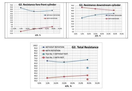
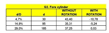
It is remarkable that at the minimum distance of about 5% of D the fore-front cylinder generates a negative resistance, which means that this cylinder is producing a positive thrust, although simultaneously the downstream cylinder presents a larger resistance.
Next cases of combined rotation speeds have been also simulated at minimum distance of 5%D:

Detailed numerical results for these cases are:
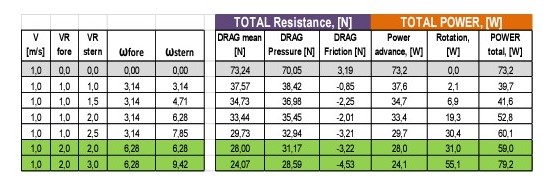
It is confirmed that synchronized rotation (case G3e.1) is the one requiring less power to keep up the forward movement.
2.3. Validation with new program of model tests.
At the end of year 2021 it was decided to validate once more ARCUSIN Principles carrying out new physical model tests at the facilities of INTA-CEHIPAR (Canal de Experiencias Hidrodinámicas de El Pardo – Madrid, España). Following tables show the tests carried out:
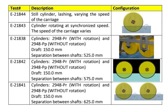
For this, the following device was developed to test 1 or 2 cylinders:
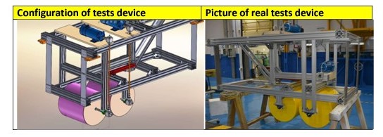
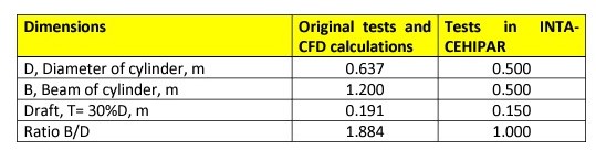
Unfortunately, and mainly due to the limited resources of this project, INTACEHIPAR used cylinder models that did not bear total dimensional similarity with those initially tested and later calculated numerically with the CFD OPEN-FOAM code. The width of the cylinders was limited to make installation on the towing carriage easier.
The main objective of the tests at INTA-CEHIPAR was to verify the ARCUSÍN Principle number 2, which is what would allow the development of a sustainable clean energy generation system. For this, the tests E-21838, E-21841 and E-21842 with two cylinders were carried out first.
But taking advantage of the test device with two cylinders, it was decided to eliminate one cylinder and carry out two new reduced tests, E-21843 and E21844, with a single cylinder WITH and WITHOUT synchronized rotation, to try to also verify the ARCUSÍN number 1 Principle.
2.3.1. One cylinder tests
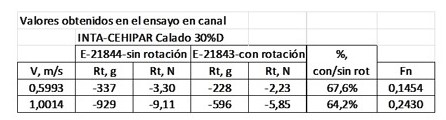
These values compare with those calculated by numerical CFD methods, even though the cylinders were not geometrically similar; for this reason, they are presented in the attached graph in values that are as dimensionless as possible:

The comparison is reasonable because, having the cylinder tested in El Pardo a smaller beam, it seems consistent that the decrease in resistance is less, but in any case a percentage of significant decrease in resistance appeared, after all.
2.3.2. Two cylinders tests
The objective of the tests with two cylinders was to measure the thrust force (of opposite sign to the resistance) that appears in the forward cylinder when it advances and rotates at synchronized speed, whether or not the aft cylinder rotates, and how it varies when the cylinders separate. The results of the tests E21838, E21841 and E21842 already defined above, carried out at different separations of the cylinders, corresponding to 5%D, 15%D and 25%D, are presented.
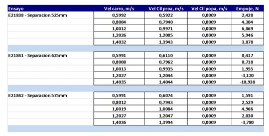
And in graphical form:
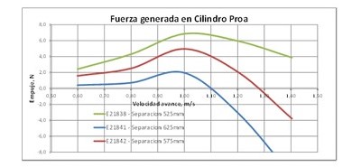
It has been verified with these tests:
⇒ That as the separation increases, the generated force decreases, so that for a 25%D separation, this force is very small, which coincides with what was obtained by means of CFD calculations with two cylinders of other dimensions.
⇒ That as the speed increases, the force generated increases until a speed of approximately 1 m/s when it begins to decrease. In the CFD calculations, only speeds below 1 m/s were analyzed because it was considered that the resulting Froude number is very high, so that the interaction phenomena between the cylinders become second order compared to the wave system that are generated by high pressures, which as is well known increases exponentially with high values of the exponent to these Froude numbers.
2.4. Conclusions at model scale
With the results obtained at model scale, both with model tests and CFD calculations, it can be concluded that ARCUSIN Principles 1 &2 are fulfilled.
3. CFD results at different scales.
The scope of the project has been extended to full scale and several sizes of cylinders have been calculated also with OpenFoam. 4.1. Cylinder geometry The form of the cylinder modelled for CFD calculations at model scale and at larger sizes corresponds initially to a perfect cylinder with sharp edges in the intersection of the planes of the bases with the lateral surface. The fluid mesh generated for this geometry has been called M2.
Having observed that the flow passing the sharp edges presented some instability a new geometry of the cylinder was developed by simply rounded the edges. The fluid mesh generated for this geometry has been called MF7. The main dimensions of the new cylinder are indicated in the next figure:
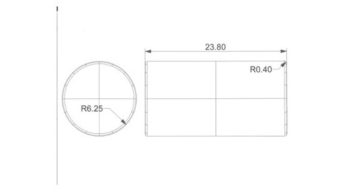
These dimensions practically maintain the proportions of the original cylinder at a scale of approximately 19,623.
3.2. Two cylinders cases
3.2.1. Cases presented.
Among the multiple cases calculated, the cases of two cylinders presented here, in order to analyze the influence of size and the possibilities of applying the laws of hydrodynamic similarity, are:
- With mesh M2, at scales 1, 5, 10 and 20.
- With mesh MF7, at scales 10 and 20.
All calculations have been carried out in configuration D (both cylinders rotating at synchronized rotational speeds) and in configuration A (both cylinders without rotation) in all cases at corresponding advanced speeds following Froude’s law in each scale.
In addition to the main purposes of this report, there is an extra objective of these calculations that is to check the influence of the rounding edges of cylinders in the advance resistance and in the power needed to maintain the movement of the system.
Following tables include the results of these calculations for each cylinder in each case. In red correspond to the cases with mesh MF7.
First data for cylinders WITHOUT rotation:
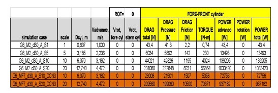

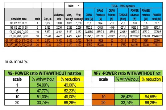
The ratio of power reduction of the condition WITH rotation over the condition WITHOUT rotation is much larger in the cases of cylinders with rounded edges.
3.2.2. Non-dimensional analysis.
With the data presented here, it is possible to represent these results in the form of dimensionless coefficients, using the standard division of the total resistance into its components, calculated directly by means of the CFD code used:
Rf: Resultant of the frictional forces in the direction of movement
Rp: Resultant of the pressure forces in the direction of movement
RT (total) = Rf (friction due to viscosity) + Rp (pressure)
In non-dimensional form it remains: CT = Cf + Cp
The same expressions that have already been explained in section 2.1.4 of this report are used.
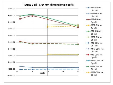
From the analysis of these results, some interesting conclusions can be drawn, which have also been verified with many other cases that are not presented here because they are not necessary:
1.- The MF7 mesh corresponding to the rounded edges is more stable than the M2 with sharp edges and, above all, gives rise to much lower values of the Ct coefficient and therefore of the total resistance.
2.- However, the value of Cf for both meshes is similar, confirming the principle of ARCUSÍN number 1, since in all cases WITH synchronized rotation this value is practically null.
3.- The effect of the rounded edges is clearly manifested in the values of Cp (and consequently in those of Ct) which is the dimensionless coefficient of the resultant of the pressure forces, which are the ones that will give rise to the wave system generated; its value is constant with the scale, Cp= 0.022 in the case of the MF7 mesh and Cp= 0.037 for the M2 mesh, both cases WITH rotation.
4. Final statements.
It can be stated as a proven fact in all calculations at model scale or larger cylinders that both ARCUSIN Principles 1 and 2 are clearly fulfilled.
In addition, several additional conclusions can be highlighted:
1. In all cases with synchronized rotation, the frictional resistance is practically nil.
2. Cylinders with rounded edges (simulated with the MF7 mesh) greatly reduce the pressure drag component (which is primarily responsible for wave making resistance). That means that the shape of the cylinders has a great influence on resistance reduction.
3. In particular, the values of Cp for the same geometry are practically constant with the scale, but its value is 0.022 for cylinders in mesh MF7 and approximately 0.038 for cylinders in mesh M2.
4. More resources should be devoted to researching various cylinder shapes and sizes to obtain results with lower values of Cp coefficient.
5. Lines of future applications of the ARCUSIN Principles.
Taking advantage of the two main aspects derived from the ARCUSÍN Principles allows us to foresee future applications. These aspects are:
1.- That the frictional resistance of a cylinder advancing on the surface of the water rotating at the speed of synchronized rotation presents practically zero frictional resistance (Principle #1).
2.- That two cylinders located in a water current rotating at the speed of synchronized rotation cause a force against the current to be generated in the bow (Principle #2).
Thus, different applications can be envisaged:
In navigation in inland waters such as waterways or lakes, a transport on rotating rollers can be investigated, which, as it does not present friction resistance, could be competitive against conventional barge transport.
In Naval Architecture, the application of a cylinder or body of revolution located at the stern of the ship could be studied, which could generate thrust on the ship, provided that the increase in resistance of the appendage itself was less.
A renewable energy generator device can be developed by installing two cylinders in a current, leaving the stern one fixed and taking advantage of the force against the current of the bow, allowing it to separate until the force disappears and stopping its rotation in this moment, the current will drag cylinder back, generating energy in each cycle. In fact, the testing device developed at INTA-CEHIPAR has the objective of investigating this line of work when funds become available.
6. References.
M. M. Bernitsas, K. Raghavan, Y. Ben-Simon, E. M. H. Garcia, 2008, VIVACE (Vortex Induced Vibration Aquatic Clean Energy): A New Concept in Generation of Clean and Renewable Energy From Fluid Flow, Journal of Offshore Mechanics and Arctic Engineering NOVEMBER 2008, Vol. 130.
M. M. Bernitsas, K. Raghavan, Y. Ben-Simon, E. M. H. Garcia, 2009, The VIVACE Converter: Model Tests at High Damping and Reynolds Number Around 105, Journal of Offshore Mechanics and Arctic Engineering FEBRUARY 2009, Vol. 131.
B. Bouscasse, A. Colagrossi, S. Marronea, A. Souto-Iglesias, 2017, SPH modelling of viscous flow past a circular cylinder interacting with a free Surface, Computers and Fluids 146 (2017) 190–212.
J. R. Meneghini, F. Saltara, C. L. R. Siqueira, J. A. Ferrari Jr, 2001, Numerical Simulation Of Flow Interference Between Two Circular Cylinders In Tandem And Side-By-Side Arrangements. Journal of Fluids and Structures (2001) 15, 327-350.
H. Miyata, N. Shikazono And M. Kana, 1990, Forces On A Circular Cylinder Advancing Steadily Beneath The Free-Surface, Ocean Enginering, Vol. 17, No 1/2, Pp. 81-104, 1990.
P. Reichl, K. Hourigan and M. C. Thompson, 2005, Flow past a cylinder close to a free surface. J. Fluid Mech. (2005), vol. 533, pp. 269–296
R. Subburaj, S. Vengadesan, 2019, Flow Features For Two Cylinders Arranged In Tandem Configuration Near A Free Surface, Journal Of Fluids And Structures Volume 91, November 2019.
C. H. K. Williamson, 1996, Vortex Dynamics In The Cylinder Wake, Annual Review Fluid Mechanics, 1996. 28:477-539.