


Summary
Early ship design stages are where most of the decisions and costs are compromised, and where 2D drawings are still widely used. The idea of using a single tool for the whole process, starting with the creation of a 3D model at early design stages, has been profusely required in naval shipbuilding. It is not easy to convince the agents involved about the advantage of having increased work at early phases, although the effort will be rewarded downstream.
This paper describes, in detail, the benefit of changing the process of ship design by using an advanced Computer Aided Design (CAD) tool from the early stages, describing how it will be an advantage in terms of quality and costs. The most remarkable benefits are the data integrity, the avoidance of long design periods and cost increases due to errors, re-work and inconsistencies.
The main challenges refer to integration at all stages and disciplines by the use of a single CAD tool. It must be effective at all stages, from the quick definition of the 3D model to the transfer of modelling information to the analysis and calculation tools.
This paper describes our findings in ship design, as an example of engineering work, using a shipbuilding oriented CAD System.
Keywords: Computer Aided Design; Basic Design; Shipbuilding; Finite Element Analysis; Ship Design.
Contents
2. The challenge of early 3D design
4.1 Surface definition and naval architecture calculations
4.3 Hull structure basic design
4.3.1 Shell and decks definition
4.3.2 Internal structure definition
4.4 Main equipment positioning
4.5 Generation of outputs from the 3D Model
4.5.1 Classification drawings for approval
5. Link with finite element tools
6. Transition to detail design
7. Benefits in area of improvements
1. Introduction
The definition of a ship project in shipbuilding usually comprises three stages, conceptual, initial/basic and detail design (seefigure 1). During the detail design stage the use of a ship 3D model is very common, while the basic design is still based on 2D drawings in many companies, although it is the stage where most of the costs are compromised which implies long design periods, repetition of relevant parts of the work in subsequent stages and a potential for multiple design inconsistencies. This all leads to a major increase in costs and a low production performance.
Being aware of this situation and also due to marketing and commercial reasons 3D tools have been introduced recently in the initial design stage. In some way, the problem could be understood as another episode of the traditional debate between the 2D and 3D approaches.
The ship design process is often shared between several design actors that develop different aspects of the engineering. The process is rather sequential as the input for some stages is the output from previous ones. A non exhaustive list of tasks normally includes:
- Development of the main hull structure based in 2D drawings.
- These drawings are sent to Classification Societies (CS) for further analysis and subsequent approval.
- In order to check the structure, CS often develop a 3D Model of the structure, based in the 2D drawings received.
- Indeterminate iterations of the process usually arise, due to the implementation of the comments from the CS into the 2D drawings.
- Detail design activities start once the structure has been approved, taking as starting point the 2D drawings to generate a 3D model that will be used for the early activities in machinery and outfitting.
- Additionally, there are other reasons to generate different 3D models like the needs for special calculations (finite elements analysis, noise, vibrations, etc) as well as the requirements for more realistic (rendered) views of the accommodation spaces.
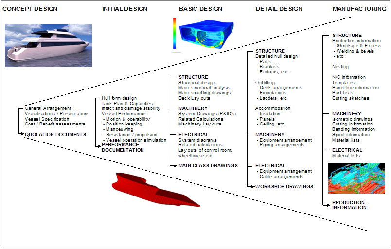
Figure 1: Design stages in ship design process
As an alternative to the traditional method, a new approach is emerging in shipbuilding. It is based on the generation of an early ship 3D model during the basic design stage, by using the same tool as in the detail and production phases. Although at first sight the detail design process might seem more time consuming, in the long run the advantages are huge mainly derived from the reuse of information. As a fundamental requirement for the solution to be efficient, the generation of the classification drawings for approval should be simple, as well as the transference of the model to the analysis tools.
2. The challenge of early 3D design
The debate about the advantages of using an early 3D model in shipbuilding started many years ago. At the beginning it was more philosophical than a real solution, because the available tools in the market were not good enough to ensure its successful use at early ship design stages. That is the reason why most part of the ship designers still work in 2D at this stage.
The approach is exactly the same nowadays, but the 3D CAD tools had to change a lot. Only by adding important and innovative new capabilities it is possible the easy generation of the 3D model.
Still with all stakeholders debating between advantages and disadvantages of 2D or 3D approach, what it is clear is that, in general, papers tend to disappear. We can see it in many industries, in many fields, which make us thinking that we are on the right path.
Having the idea clear in our minds, the true is that concept and basic design stages are very demanding in terms of time. If a design team would have all the time, they would build a 3D model even with a no very useful tool. But the true is that at this stage the time is short, and the demand of information and quality is great. Here is where this approach has much to say, because the 3D approach ensures the quality and avoid errors and inconsistencies inherent to the 2D approach.
Regarding the time, the 3D tools need to be provided with capabilities oriented for simplicity and automation. The decrease number of clicks, modules and commands are absolutely essential.
With this, the possibility of generating at early 3D model accurate but quick enough to be competitive with the 2D approach is possible. Later on, the re-use of information with a seamless transition to the detail design convince, because the approach needs to be understood as a global process. The estimation of real weights and the exact positioning of the main equipments are other advantages that play a fundamental role.
3. CAD system philosophy
The key aspects of a Shipbuilding CAD System, i.e. FORAN, which makes possible this approach are described in this chapter:
- Database: It is built on top of a relational database which ensures a single true source of data during the whole design process
- Topology: The possibility of introducing quick changes that can be propagated through the model with a single click is possible thanks to the topological approach. This is specifically relevant at early ship design stages, when important changes are introduced into the project, and where important decisions need to be made having as much real information as possible
- Integration: All disciplines are totally integrated, in a single environment. So, the early 3D model of structure is generated with the same tool that for the detail approach. The reuse of information is absolutely critical. Thanks to this, the amount of effort during the detail design stage is substantially less.
At the end of the process, the results in terms on quality and time are much better.
The proposed solution is based on a 3D ship product model, see an example of a block being building on figure 2, in which the geometry and the attributes of the elements of the ship are stored. The model is built as an essential part of the engineering work, can be visualized at all stages and can be exploited to obtain information for material procurement and for production. The main characteristics of the ship product model are discussed in the following paragraphs.
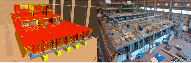
Figure 2: 3D model where checking & manufacturability rules are embedded in a CAD System Design Tools
Building and early 3D model in a shipbuilding oriented CAD System allows to improve the design process of the ship and to study different design alternatives in shorter periods of time, which reduces both delivery schedule and cost.
As a result, it is possible to reach a better performance when developing the design and, at the same time, to obtain a product of high quality in a very competitive way. The FORAN solution is based on the integration of all the design stages and disciplines, thanks to a single database, which moreover permits the implementation of collaborative engineering and guarantees the information integrity (Rodríguez, 2000).
The definition of the model is easy, thanks to the advanced functions implemented in a shipbuilding oriented CAD System. The use of a topological model instead of a geometrical model, facilitates its definition, allows the quick study of different design alternatives and simplifies the modifications, which are very common in the early ship design stages. The main advantage of the topological definition, where geometrical data are not stored but calculated on-line, is that changes in the main hull surfaces are automatically incorporated in the modified elements, just by reprocessing them. In addition, the topological definition allows the existence of powerful copy commands making thus the definition far more efficient than working only with geometry. Another benefit of the topological model is the size of information stored in the database, much less than for geometrical models.
The key aspect of the design process is the definition of a single ship 3D model, accessible for several designers working concurrently, to be used in all stages of the ship design. While the project is progressing, the level of detail is increasing and the different parts of the model are subdivided by means of a progressive top-down definition. The solution delivered by a shipbuilding oriented CAD System includes tools that facilitate the direct transition from basic to detail design, by means of simple operations that include blocks splitting, the assignment of parts to blocks and the completion of the model with attributes for the manufacturing phase.
4. Basic design process
The basic design process in a shipbuilding oriented CAD System begins with the forms file definition, hydrostatic calculations, definition of volumes, characterization of the intact and damage stability conditions and other naval architecture concepts. Later on it is necessary to define the material catalogues describing plates and profiles to be used in the design. Once the hull forms, decks, bulkheads and other surfaces are created, the hull structure module is used to create the major openings in all surfaces, the scantling of the main surfaces for plates and profiles as well as the main structural elements (floors, web frames, girders, stringers, etc.).
The definition is usually based in the frame and longitudinal systems which allows a full recalculation of the model in case of changes in the spacing between elements.
In early stages, plates and profiles are created as objects representing zones of a surface with common scantling properties. Therefore, the size of the objects is not consistent with the manufacturability, which will be considered in later stages of the design. Other properties like the continuity and watertightness attributes of surfaces or parts of them can be defined at any time.
The sequence of the definition of the model in a shipbuilding oriented CAD System has a high degree of flexibility being possible to create both plates and profiles at any time. However, designers would normally follow the same rules as when working in 2D, which means to start with the definition of the continuous elements because this will allow the automatic splitting of the non-continuous elements (Aarnio, 2000).
The assembly break down to unit or block is optional at this stage, and the level of detail of the 3D model is the one required by the classification drawings, with respect to the type of parts included (brackets, face bars, clips, collars, etc.) as well as to other characteristics (profile end cuts, scallops, notches, etc).
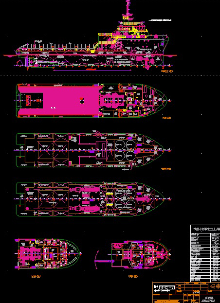
Figure 3: General Arrangement of a ship using a CAD System
4.1 Surface definition and naval architecture calculations
Ship moulded surfaces model includes the external hull form, decks, bulkheads, appendages and superstructures. Under a shipbuilding oriented CAD System, the geometrical representation for all the surfaces is a collection of trimmed NURBS patches, Bezier patches, ruled surfaces and implicit surfaces (planes, cylinders, spheres and cones). The surfaces can be imported from files using different generic formats, such asiges and the AP-216 of the step format.
FORAN, as an example, has two complementary tools for surface definition. The traditional tool permits the definition of the hull surface, either conventional or special forms, such as non-symmetrical ones, multi-hull and offshore platforms. This tool includes advanced fitting and fairing options and allows several transformations of the hull forms (based in block coefficient, longitudinal position of the centre of buoyancy or quadratic) and other operations like lengthening or shortening of a ship that can be easily performed.
This CAD System has incorporated recently an additional tool based in the latest-generation of mechanical design that can be used for improving hull forms.
The intensive use of topology makes possible the automatic recalculation of all elements when a modification is performed in upper level concepts (hull and decks surfaces or material standards). This type of topological definition produces important time savings during the development of the basic design, where the modifications are frequent.
Once the surfaces have been defined, it is possible to analyse the hydrostatic and stability calculations. For these naval architecture purposes, it has been developed a new module called FBASIC that groups in a single solution the former modules.
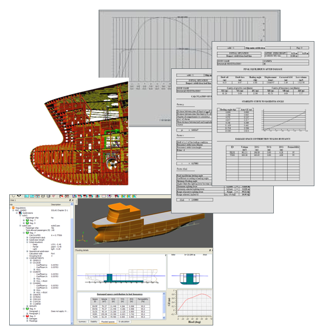
Figure 4: FBASIC, one of the latest tool for advanced naval architecture calculations
4.2 Volume definition
The next step in the basic design definition is to define the compartment arrangement of the project. It will be based on the definition of spaces. Each space will be represented by its 3D model.
Also, it has been developed a new module called FGA. This module is dedicated to define and manage the compartment arrangement of a project. A 3D model of the spaces will be generated taken as reference the surfaces of the ship as well as auxiliary planes. It is also possible the definition of spaces from 2D drawing in a specific definition environment. Compartment arrangement defined on FGA will be available in FBASIC module for hydrostatic and stability calculations.
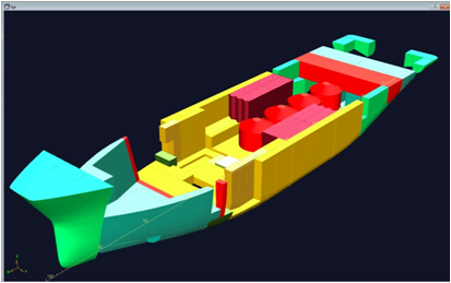
Figure 5: Realistic visualization of space definition using FGA
4.3 Hull structure basic design
4.3.1 Shell and decks definition
This 3D curved surfaces context allows the definition of plates, profiles and holes. Work division is made by using the surface and zone concepts, which allows the multi-user access to any surface. A general zone may be used to contain the entities common to several zones. The following type of profiles can be defined:
- Shell and deck longitudinal
- Frames and deck beams
- General profiles
Profile definition is mainly based on topological references to already existing structural elements, as well as to auxiliary concepts used in the early stage of the design (longitudinal spacing, frame system, other profiles, etc). The user can easily assign different attributes such as material, scantling and web and thickness orientation. These basic attributes can be completed by adding constructive attributes (parametric web, flange end cuts, etc) at any time of the design process. The profiles can be split up in profile parts later, when the transition from basic to detail design is performed. Profiles crossing other profiles will automatically generate the necessary cut-outs and scallops (Alonso, 2013).
All types of profiles including flat, curved and twisted are represented as solids. Web, flange and the corresponding end cuts are displayed with a user configurable degree of accuracy.
Due to the intensive use of topology, the definition of the shell and deck plating can start in the early stages of the design, even with a preliminary definition of the hull and decks. In this regard, the basic concepts are:
- Butts: Lines lying on a surface used as aft and fore limits for the plates. Butts can have any shape or be located in transverse planes at any abscissa.
- Seams: Lines lying on a surface used as lower and upper limits for plates, with any geometric shape. Seams are usually defined by means of a set of points on the surface and some additional rules to define the layout.
- Plates: zones of the surface defined by aft and fore butts, and lower and upper seams, with attributes such as gross material, thickness and, optionally, bevelling/edge preparation, construction margins and shrinkage factors. Plates can also be the result of breaking down an existing plate in two smaller plates.
Flat and curved plates are represented as solids (including thickness) and the information for plate pre-development is automatically generated allowing thus an early material take-off list.
4.3.2 Internal structure definition
The internal structure context is based on the same high performance topological and visualization environment of the curved surfaces, but applied to a section lying on a plane. This environment provides a set of advanced functions for the easy definition and modification of plates (flat, flanged and corrugated), straight and curved stiffeners, holes, face bars, standard plates, on and off plane brackets, collars and others.
It is possible to have several sections in memory making easy operations, like copy or multiple editions of elements in different sections. The work division is made by using the section, structural element and zone concepts, which allows multi-user access to any section (Alonso, 2013).
As an example, you can see in figure 5 a basic design patrol vessel created using the structure module in this shipbuilding oriented CAD System, FHULL.
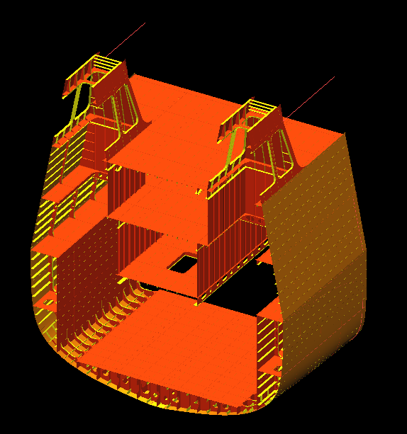
Figure 6: 3D model of one of the warship blocks created for this paper
The main features are:
- Predefined best practices support through the use of structural element concept, defining default constructive values and parameters for plates, profiles and face bars
- Automatic part splitting, using the crossing/not crossing structural element attribute
- High productivity tools, like one click plate definition, reduction to the minimum of the auxiliary geometry and join and split functions for plates and profiles
- XML based high performance topological definition language for the definition of plates, profiles and face bars
- Profile and face bars definition using standard profile cross-sections, parametric cut-outs and parametric web and flange end cuts
- Automatic cut-outs insertion for both plates and profiles
- Standard or free shape holes definition and automatic application to the affected plates
- High productivity commands including split, multi-edit and multi-copy for both plates and profiles in the same or in different sections and structural elements
4.4 Main equipment positioning
Once the structure has been defined over the hull forms, it is the time for outfitting and electrical disciplines. The key action is to place all the main equipments, as for example, main engines, reduction gear and propeller shaft. Other equipments also include in the basic design are equipments with huge volume and/or surface. Electrical equipments as auto generators and transformers, or outfitting equipment as big water ballast systems could be positioning for initial stability calculations.
4.5 Generation of outputs from the 3D model
The next paragraphs describe the tangible outputs derived from an early hull structure 3D model like drawings, reports and models to be used in the analysis and calculation tools. In addition, there are other important outputs; in fact the existence of a 3D model makes more efficient the tasks related to the outfitting basic design.
4.5.1 Classification drawings for approval
Although the approach described in this paper is more general, any improvement in the process of basic design must consider the fact that the main output during the hull structure basic design stage is to obtain the classification drawings for approval. Classification drawings are symbolic drawings of different types, like:
- Shell and deck drawings (different views, including expansion)
- Typical planar sections
- Other detail drawings
The drawing generation in a shipbuilding oriented CAD System is managed normally by a single module, which covers the output drawings of all design disciplines (general, hull structure, outfitting, electrical and accommodation). The drawing generation is completely user configurable, as the final aspect of the drawings depends on the user requirements. Drawings are generated directly from the 3D product model, and the 2D entities that represent the product model are linked to the 3D elements, and are always updated with the latest version of the product model. A symbolic representation for modelled elements is possible and different visualization methods are available (García, 1994).
The drawing generation module includes also a function to reprocess the drawing after changes in the model, and at the same time keeping any manual modifications introduced by the user in the drawing.
There are also options for automatic dimensioning and labelling by means of user-configurable formats and templates representing different attributes of the selected elements (identification, scantling, profile cross sections, end-cuts and others). These entities are also linked to the product model elements. The drawings generated are compatible with most of the standard drawing formats too.
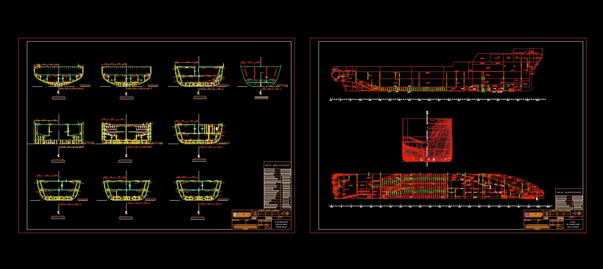
Figure 7: Example of Classification Drawing made in a CAD System
4.5.2 Other outputs
One of the advantages inherent to integrated 3D applications refers to the easiness of data extraction as the whole product model is stored on a single source of information. Different types of reports that can be generated are configurable and can be exported to most of the standard formats like Excel, HTML and ASCII.
Fixed contents reports like steel order (plates and profiles) and configurable bill of materials can be obtained based on query conditions decided by the user. Report contents will depend on the degree of definition of the project (Rodríguez, 2000).
Among others, the following reports can be obtained in a shipbuilding oriented CAD System:
- Weight and centre of gravity
- Painted areas
- Material takes off lists
- Bill of materials
- Welding lengths
5. Link with finite element tools
One of the most relevant aspects during the basic engineering of a ship is the structural analysis by means of the application of the finite elements method (FEM), which makes possible to improve and validate the feasibility of the design. In practice, it is a laborious task that requires the preparation of a suitable model for calculation, meshing, the application of loads and constraints, processing, post-processing and analysis of the results (Aarnio, 2000).
Most of the finite element tools include standard formats for the direct import of 3D CAD models, but they fail when these models come from the shipbuilding industry due to the complexity of the ship models. The effort required in the manual simplification of the model is such that it is more efficient to repeat the model with a calculation-oriented approach, which slows down the analysis process dramatically.
The use of a ship model already created in a 3D CAD for FEM analysis would optimise the design performance in the early stages. For this, there must be an efficient link between both tools so that a simplified ship model adapted to each type of calculation can be exported directly from CAD.
Our approach to this problem combines its broad experience in the development of a CAD/CAM shipbuilding tool with innovative solutions to obtain the expected results: a link that makes possible to export a simplified ship model, leveraging its topological characteristics. Functional algorithms in a shipbuilding oriented CAD System allow the creation of an intelligent model, simplifying, filtering and deleting unnecessary data to guarantee the quality of the model transferred.
Among other functionalities, the user can decide:
- Whether the plates are translated as surfaces by the neutral axis or the moulded line
- The automatic assignment of colours to every material and profile scantling
- Whether the profiles will be translated as surfaces or as curves
- The minimum area to discard the transfer of holes and brackets
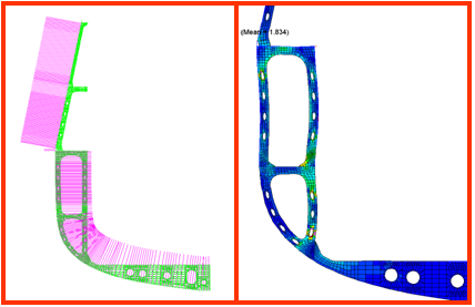
Figure 8: 2D Finite Element model produced using CAD System FEM-link, to check scantlings and optimize structure
All structure entities will be subject to an idealization process aiming to simplify the 3D model by using the following criteria:
- For plates, notches, scallops, fillets and chamfers will be removed from the outer contour
- For profiles (either via surfaces or curves), notches, scallops, macro-holes, end-cuts and profile extensions will be removed
- Surfaces created as plate or profiles are extended topologically to the moulded line/neutral axis of the surface used in its definition. This simplification is applied on every intersection line with other surfaces used in the plate or profile definition
- Plates are splitted in different surfaces using the profile layout and any other marking line
- Corrugated and flanged plates are splitted in planar faces
- Surfaces sewing, every two surfaces created by a previous one split will be sewn on the join line
- Profiles sewing: If the profile is translated as a surface, flange and web will be sewn. Translated profile web surface will be sewn to its underlying plate surface too
- Plate limits are extended to the surfaces used in its definition
6. Transition to detail design
The key point to for any software solution aiming to provide a complete solution for ship design and manufacturing is the capability to provide smooth transition between the stages of the design avoiding rework and delays. Thus, as a logical continuation of the basic design, a CAD System provides tools for subdividing and joining plates and profiles, and also features additional attributes for detail design such as bevelling, construction margins and shrinkage factors, and also for defining parts that are not relevant during the basic ship design stages.
The way from the initial to the basic and the detailed design is also the way from the conceptual and abstract to the concrete and manufacturable. Large conceptual parts useful to analyze for instance weight and structural behaviour must be converted in manufacturable parts reusing all the information provided in the conceptual stages and detailing when necessary.
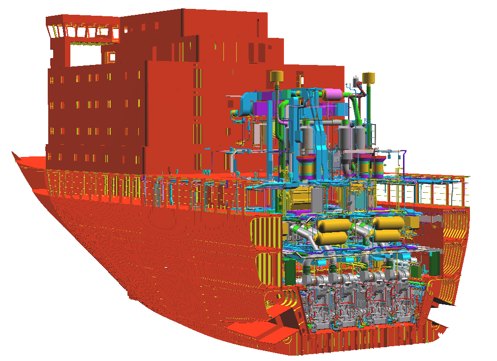
Figure 9: Snapshot of a 3D detailed model, with outfitting, cable trays and structure integrated
The split concept is basic in this transition, for example large longitudinal layouts are splitted into manufacturable profile parts inheriting layout attributes and with the appropriated split properties according to end-cuts, margins, etc. The split concept is applied to any kind of part, from bulkhead profiles to curved hull plates.
The level of detail not only concerns geometry but also attributes. Part attributes irrelevant in conceptual stages become critical in detailed design. In order to provide a smooth transition, tools to modify, check and copy attributes of large groups of pieces are provided.
The block subdivision is perhaps one of the most critical points in ship design regarding the transition between ship design stages. Although split and refinement tools can be used for block subdivision, some specific tools are provided in order to perform automatic recalculation of parts when the block butts are modified. Assignment of parts to units can be done at any time by means of a powerful graphical selection tool.
Finally, in this stage it is the right time to complete the detail design by defining those parts which are not relevant for the basic design stage.
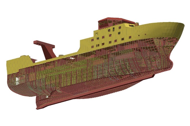

Figure 10: FEM analysis in a FORAN Project
7. Benefits in area of improvements
The benefits of this approach are listed below:
- Shorter evaluation of different design alternatives due to the high level of topology that allows an automatic recalculation in case of upper level modifications.
- The generation of a 3D model at early ship design stages allows to take decisions having real information instead of estimations. Early estimation of materials and weights, including welding and painting
- Less risk of inconsistencies comparing to the 2D approach in which every view is independent and has no relation with the others. Instead, the 3D approach combines the implicit intelligence associated to the model by means of certain attributes (continuity, watertightness) with the graphical checking performed by the user leading to a design with better quality
- Easier link with analysis and calculation tools based in the existence of a single 3D model that, for the purpose of other calculations, is subject to an idealization process for easier management in the FEM/FEA tools. Most part of these calculations are made during the basic design stage
- The quick position of the most relevant equipment helps in setting the most important spaces of the ship and also for weights and centres of gravity considerations
- Due to the incremental development of the model as the design evolves, there is a seamless transition to detail design based in the reuse of data which reduces the design time and simplifies the overall process
- More accurate design due to the use of a 3D tool
- Easier co-ordination among disciplines as hull structure and various disciplines of outfitting are represented in the same underlying product model. This has obvious advantages in terms of interference or collision checks and leads to a better outfitting design regarding the general arrangement definition and critical compartments layout
- Having the 3D model at early ship design stages allows the navigation around it using Virtual Reality viewers. This is an important advantage for marketing activities or to control the design process in a very intuitive way

Figure 11: Virtual reality navigation using 3D glasses around a ship 3D model in FVIEWER
Some areas of improvements are:
- The more simple the generation of the 3D model is, the more benefits are obtained. There are things to improve in reducing and simplifying the generation of the model
- The solution need to be flexible and easy to use. The people involved in the concept and basic design is usually working with 2D tools, which are very easy to use. For them it is crucial to have a very useful tool
8. Conclusions
A CAD System improves design quality, provides higher precision and reduces the risk of inconsistencies. The rapid evaluation of several design alternatives and the early estimation of materials, weights, welding and painting are additional advantages, in addition with the efficient link with finite element analysis tools. Finally, it also facilitates the definition of the outfitting (general layout and layout of critical compartments) and improves the coordination between disciplines. In conclusion, the key points are the simple transition to detail design and the reuse of information.
This substantial change in the development of the basic design stage, which is now being required and implemented, is expected to become the routine way of working in the future, particularly when the continuation with the detail design is considered and/or outfitting design is part of the scope of work.
It is well known that most of the costs of a ship are compromised during the initial design stages. The proposed solution delivers tangible benefits as it optimizes the process by reducing the time dedicated to design and consequently the cost.
9. References
Aarnio, M. ‘Early 3-D Ship Models Enables New Design Principles and Simulations’. 1st Int. Conf. Computer and IT Appl. Maritime Ind. (COMPIT), Potsdam 2000.
Alonso, V; Gonzalez, C.; Pérez, R. ‘Efficient use of 3D tools at early design stages’. COMPIT. Cortona 2013.
Garcia, L; Fernandez, V; Torroja, J. ‘The Role of CAD/CAE/CAM in Engineering for Production’. ICCAS, Bremen 1994.
Rodriguez, A; Vivo, M ; Vinacua, A. ‘New Tools for Hull Surface Modelling’. COMPIT. Potsdam 2000.