
Scale effects in open water test results for performance prediction of conventional and unconventional propellers
Mariano Pérez-Sobrino1,*, Juan González-Adalid1, Ramón Quereda2, Cristina Soriano2, Amadeo Morán3, Giulio Gennaro4
1SISTEMAR, Madrid, Spain
2INTA-CEHIPAR, El Pardo Model Basin, Madrid, Spain
3CEHINAV, Universidad Politécnica de Madrid
4SINM, Genoa, Italy
*Corresponding author, E-mail: mps@sistemar.com, Tel.: +34-630288684.
Abstract
ITTC’78 Performance Prediction Method is the only existing standard procedure approved by ITTC to carry out predictions of ship performance based in model tests results. It has been successfully applied from 1978 by towing tanks directly or introducing some variations. But it has been explicitly recognized by ITTC that this method must be only applied to conventional propellers and cannot be applied to Unconventional Tip Shape propellers.
This kind of propellers is one of the best options to save energy in marine propulsion. However, as at model scale these improvements are not clearly shown, the lack of a standard procedure to be applicable to this type of propellers reduces in many projects the possibilities to implement energy saving propellers.
In this study a new procedure will be explained in detail going a step deeper in the basic principles of viscous effects depending of the local section Reynolds number.
The validation work here presented confirms that ITTC’78-PPM is not useful to predict propulsion characteristics of unconventional tip shape propellers and that present proposed method predicts with reasonable accuracy propulsion characteristics of conventional and unconventional propellers, monoblock or CPP type and it is repetitive and easy to implement.
Keywords: Propellers, performance prediction, open-water tests, model to ship extrapolation, unconventional tip blade shape.
Resumen
El método ITTC’78-PPM es el único procedimiento estándar aprobado por la ITTC para llevar a cabo predicciones del comportamiento propulsivo del buque basadas en ensayos con modelos. Para hélices convencionales ha sido aplicado con éxito desde 1978 por los Canales de Experiencias directamente o con variaciones; pero ha sido reconocido por la propia ITTC que no se puede aplicar a los propulsores con formas no-convencionales del extremo de las palas.
Este tipo de hélices es una de las mejores opciones para ahorrar energía en la propulsión de buques. Sin embargo, los ensayos con modelos no detectan estas mejoras directamente y por consiguiente la falta de un método aceptado reduce las posibilidades de instalación de estas hélices con mejores rendimientos.
En este trabajo se explica en detalle un nuevo procedimiento avanzando un paso más en los principios físicos de la resistencia viscosa que depende del número de Reynolds local.
La validación realizada confirma que el método ITTC’78-PPM no se puede usar para hélices no-convencionales mientras que el método propuesto predice con una precisión razonable el comportamiento propulsivo de hélices convencionales y no-convencionales, sean de paso fijo o CPP, y que tiene un carácter repetitivo y es fácil de implantar.
Palabras clave: Propulsores, predicción del rendimiento propulsivo, ensayos de propulsor aislado, extrapolación modelo-buque, formas de extremo de pala no-convencionales.
Cita:
Pérez-Sobrino, Mariano; González-Adalid, Juan; Quereda, Ramón; Soriano, Cristina; Morán, Amadeo; Gennaro, Giulio. “Scale effects in open water test results for performance prediction of conventional and unconventional propellers”. Ingeniería Naval Académica. 2016. Nº 5. Disponible en web: <http://sectormaritimo.es/numero-5-abril2016>. ISSN: 2340-4779
CONTENTS
Abstract (English) & Resumen (español)
- Introduction
- Description of the new open water scaling procedure.
2.1 OW corrections according to ITTC’78 PPM.
2.2 Different possible approaches.
2.3 Development of new procedure.
2.3.1 Basic formulation.
2.3.2. Viscous resistance coefficient of a section blade.
2.3.3. Friction Coefficient at model scale.
- Validation of new method.
3.1. Application to conventional propellers.
3.2. Application to unconventional propellers.
- Conclusions.
Nomenclature
References
APPENDIX A- Detailed calculations for Conventional propellers
Case study A1- Propeller CEHIPAR-2480, CP Propeller type. 4 blades.
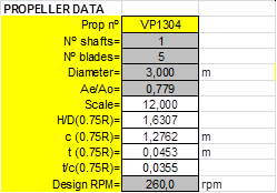
Case study A2- 28th ITTC Benchmark CP propeller VP1304. 5 blades.
Case study A3- Propeller CEHIPAR-1697, FP Propeller. 6 blades.
APPENDIX B- Detailed calculations for Unconventional CLT propellers
Case study B1- LEG Carrier 12k cbm.
Case study B2- Twin shafts Ferry “FORTUNY”.
- Introduction
ITTC’78 Performance Prediction Method (1) (ITTC’78-PPM) has been successfully applied, directly or with some variations, in many Institutions, Towing Tanks and specialized companies from 1978 when it was recommended to be used by ITTC. This method includes a procedure to extrapolate propeller open water tests (OWT) results of conventional propellers from measurements at model scale to predictions at full scale. This has a large influence in the final values of power, rpm and propulsive coefficients predicted for full scale. However last ITTC Reports on propellers (2) have recognized that this method cannot be applied to others than conventional propellers, and in consequence have recommended to full Conference (that represents a very important part of the Hydrodynamics worldwide Community) to develop a standard procedure for the open water hydrodynamic characteristics scaling applicable to unconventional tip shape propellers as CLT, Kappel and tip raked type propellers.
Basic principle to apply corrections to OWT model results is the different Reynolds number of the model tests compared to full scale operation. That means that viscous effects in propeller blades are also different. In consequence propeller open water parameters KT and KQ measured at model scale must be corrected to obtain appropriated values to be used for predictions at full scale. Correction method for conventional propellers implemented in ITTC’78-PPM was based in an extensive work during several years before recommendation analyzing a lot of correlation data for many types of ships for which model tests and sea trials data were available (for instance see (3)). For new types of unconventional propeller blades this is not the case; there are not so many published data to allow sea trials results to be correlated with model tests results.
It is a fact that unconventional propellers have proved in many cases at full scale that ship propulsion efficiency increases with these types of propellers when comparing to conventional propellers; however at model scale this improvement is not clearly shown and therefore it is neither shown in the standard predictions of many experimental facilities. The lack of a standard procedure to be applicable to this type of propellers is many times an obstacle to the possibility to implement energy saving propellers. Perhaps for that reason a considerable amount of work has been made in recent years on this question.
In this study a new procedure based in the strip method will be derived to compute OWT corrections by applying different expressions of the friction line more in accordance with the expected type of flow in each section of the propeller blade, depending of the section Reynolds number. The simplification of equivalent profile in which ITTC’78-PPM is based will not be used anymore. So this new strip method would substitute only the calculation of OWT corrections but other components of ITTC’78-PPM will remain without changes.
The objectives of this report are two:
Develop and describe in detail a new method to compute OWT corrections, being repetitive and easily applicable to any kind of propeller, conventional, end plate, curved rake tip, etc.
Validate this method by applying it to a comprehensive set of propellers of conventional and unconventional types which data are available to the authors.
Put a set of data relative to CLT propellers at the disposal of interested researchers.
- Description of the new open water scaling procedure
2.1 OW corrections according to ITTC’78 PPM.
ITTC’78 method is used to predict rate of revolution and delivered power of a ship from model tests results. Viscous and residuary resistances of the ship are calculated from the model resistance test assuming the form factor to be independent of scale and speed. Standard predictions of rate of revolutions and delivered power are obtained from the full scale propeller characteristics. These characteristics are determined by correcting model values measured in OWT. These corrections are based in the assumption of the equivalent profile, substituting the whole blade for the station at 0.75 radius. Hence the propeller characteristics KT(J) and KQ(J) measured in Open Water model test have to be scaled to full scale using the following expressions:
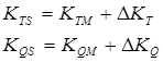
Where:
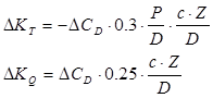
The difference in drag coefficient DCD is:
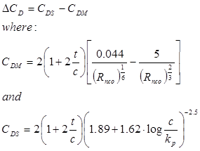
In the formulae listed above D is propeller diameter and Z is number of blades of propeller, c is the chord length, t is the maximum thickness, P/D is the pitch ratio and Rnco is the local Reynolds number at x= r/R= 0.75. The blade roughness kp is put to kp=30.10-6 m. Rnco must not be lower than 2.105 at the open-water test.
All these formulae have been derived by using the equivalent profile theory that is a simplification of the blade element theory applied to the station x= 0.75.
Following main remarks must be taken into account about OWT corrections implemented in ITTC’78-PPM:
1.- This method is not able to distinguish different blade geometries due to the assumption of equivalent profile theory. In particular, is not applicable for unconventional tip shaped propellers but even in case of blade geometries different from the “standard” type in use in the 1970’s there can exist some inaccuracies. But this is a general method for conventional propellers very easy to apply and gives a good approximation to predict full scale performance from model tests within a large range of propeller diameters and model scales. Any new method that could be developed must give for conventional propellers similar corrections for scaling Open Water tests results.
2.-The condition that Rnco must not be lower than 2.105 at the open-water test is the criterion generally accepted in order to avoid that laminar flow will be developed over the blade. But as this condition is usually applied to section 0.75R this not assures that there is not a significant part of the blade with laminar flow at lower radius.
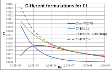
Figure 1: Comparison of different formulae for CF.
- It must be noticed that CDM is calculated as function of Rnco, whilst CDS is calculated based in the well-known formula derived by Prandtl and Schlichting for fully turbulent flow over roughness plates for high values of Rn where CF values became independent of Rn. The assumption was that full scale blades had larger roughness than propeller models. Nowadays Class requirements for finishing of propeller blades have improved and it is not clear that this formula can be used for all cases.
- However formula used for CDM (or CFm) is a pragmatic approach that generates similar values that other formulae at turbulent Rn (>1.0 x 10⁷), where it is not to be used, but at Rn corresponding to model tests (around 1.0 x 10⁵) it matches the expression of Blasius for laminar flow, but it has a slope that avoid larger values of CFm in case that Rn of model would be lower than this value (Fig. 1). For model tests at Rn <1.0 x 10⁵ it can produce results with no technical sense.
- Calculations of OWT corrections according to ITTC’78-PPM must fulfil the conditions established in this procedure; but for different reasons sometimes the size of the model is not adequate or the value of rps of the test does not assure that laminar flow is not present. And in some marginal cases, when D of model is relatively small and rps of OWT are not high enough, the application of this procedure can generate corrections out of technical sense. A new version of this procedure that could take into account all this would be very useful.
2.2 Different possible approaches.
A new method must be developed trying to contribute to solve the problem that OWT corrections in ITTC’78-PPM, being based in the approach of the equivalent profile, that identifies the behavior of the whole blade with the behavior of the blade cylindrical section at 0,75R, make impossible to distinguish advanced forms of blade propellers like end plate, tip raked, etc.
Three main approaches have been published in recent years:
- A) Semi-empirical methods. A good example of this method is the procedure published and applied by SISTEMAR and CEHIPAR to CLT designs (4). This method was based on the addition of new correlation coefficients for propeller blade and for end plate to the formulation used in ITTC’78-PPM. These coefficients have been adjusted to obtain a good correlation with sea trials results.
- B) Strip methods. The scaling is achieved by dividing the propeller in a series of chord-wise “strips”, by calculating the “local” scale effects on each strip, and finally by integrating the “local” scale effects in order to obtain the “global” propeller scale effects. An example of these methods has been published (5) and it is applied at present in HSVA also in case of non-conventional propellers. There are several variants of this method depending mainly of the treatment of how to calculate CD for model scale tests.
- C) CFD based methods and/or Panel Methods. There are also several variants of these methods and several commercial or in-house developed available codes. General approach to use these methods to compute OWT corrections is to compute independently for model scale and full scale cases and correlate the results. This usually implies to use different mesh sizes, different turbulent models, to use of transition modelization or not, etc., being by the moment needed intensive use of large resources and time demanding. As the results depend not only of the code but of the user, it is very difficult to homologate a “standard” that can be used for many people with same results. Quite a lot of research have been done for conventional and tip loaded propellers (7,8). Propulsion Committee of ITTC has at present open a benchmarking CFD exercise to compare results of different institutions using the same unconventional tip loaded and bent propeller P1727 designed by SVA Potsdam for an ongoing research project.
2.3 Development of new procedure.
The procedure presented in this study belongs to approach B). In this section a new method will be derived applying different expressions of the friction line more in accordance with the expected type of flow in each section of the propeller blade depending of the local Reynolds number. The simplification of equivalent profile will not be used anymore.
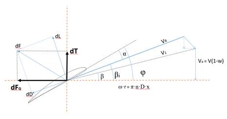
Figure 2: Diagram of velocities and forces in a blade section.
2.3.1 Basic formulation.
Starting expressions to derive the influence of viscosity in OW scaling came from blade element theory (see fig. 2):
![]()
![]()
![]()
CD values are different in model tests and in full scale operation due to differences in Reynolds number and consequently different type of flow developed over blade surface. So assuming that there are not scaling effects in Lift, we can express the influence of a variation in CD in OW coefficients:
![]()
![]()
The Open Water coefficients KT and KQ:
![]() and
and ![]()
![]() and
and ![]()
These corrections of the OW coefficients can be directly calculated from:
![]()
![]()
According to Fig.2 we can assume:
![]() and
and ![]()
![]()
We can also assume that cos(bi-b)=1, which is perfectly valid for slightly and moderately loaded propellers, being:
![]()
so:
![]()
And changing to the non-dimensional radius x=2r/D:
![]()
![]()
Here epw means end plate width; and it express that the upper limit of the integral must be extended to the end of the tip plate if any.
In order to apply more easily this procedure, it could be convenient to use βi≈φ where:
![]()
With these hypothesis calculations of dKT and dKQ can be made with only the geometrical data of the propeller blade as input:
![]()
![]()
These formulae are valid for original CLT type propellers. Generalizing for propellers with any type of rake distribution (including CLT type) the integration must be performed using a non-dimensional curvilinear coordinate representing the length of the arc of the curve from the hub to the section considered (see fig. 3). In this way it is taken into account the differences in blade area generated by different rake distributions. It is indifferent to this procedure if the blade profiles are arranged in cylindrical sections or in conical sections arranged to be perpendicular to the rake line because it has no effect in the viscous resistance of the profile.
Of course the relationship of variables x and s will depend of the type of rake distribution used.
All geometrical parameters used in these formulae, chord (c), pitch angle (φ) and thickness (t) correspond to each blade section, being necessary to know their distribution along the whole blade to perform these calculations. In this way this procedure will take into account different geometries of propeller blades.
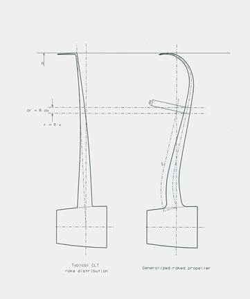
Fig. 3. Different rake distributions.
2.3.2. Viscous resistance coefficient of a section blade.
The main question is how to determine d(CD) that is the difference of viscous resistance of each blade section when operates at model scale and at full scale.
δ(CD)= CDs – CDm
It is well accepted that for the hydrodynamic profiles used in the propellers blade sections:
![]() and
and ![]()
CFm and CFs are frictional coefficients of blade sections profiles that have been widely investigated in the past. These coefficients depend mainly on Reynolds number, surface roughness and type of flow developed.
In this procedure instead of to distinguish between model and full scale, and due to the good characteristics of blade finishing both at model and full scale nowadays, the question is to determine if the flow is laminar, or if it is in the so called transition zone or if it is fully turbulent.
For fully turbulent flow the well-known formula due to Prandtl and Schlichting for smooth plates can be used both for model and for full scale:
![]()
where Rn is computed for each section blade. At ship scale the flow is generally turbulent, being:
These values are calculated using propeller rpm (rps) at design point.
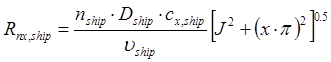
2.3.3. Friction Coefficient at model scale.
But the problem appears at model scale; there are differences between different facilities on how to carry out OWT, although most of them try to follow ITTC procedures and recommendations (Rnco>2.105), this does not assure that flow in some part of the propeller blade could not be laminar or transitional. Paint tests carried out from some years ago and nowadays CFD calculations confirm also this fact.
In any case for model scale local Rn values computed for each annular section are also used:
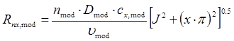
These values are calculated using propeller rpm (rps) of the Open Water tests that are usually carried out at constant rps varying carriage speed to measure at different J values.
When flow can be considered as laminar, the formula to be used is the well-known expression due to Blasius for laminar boundary layers on smooth surfaces [9]:
![]()
For the purpose of this procedure and after the analysis of several cases of conventional and end plate propellers it has been established that there exists at each blade section a critical value of Rn to change from laminar regimen to transition zone, and that there exists another critical value of Rn above of that the flow is fully turbulent. These values depend mainly on the relative surface roughness of model blades as explained in the following:
Laminar flow. It is considered that flow will be always laminar until the critical Rn number:
![]()
Where c is the chord of the blade section at model scale and kp is the roughness of the propeller model. It has been considered kp= 20.10-6 m due to the better precision got in model fabrication nowadays.
That means that if a blade section is operating at Rn lower than this critical value (which depends also on the value of the chord at model scale) all the section is considered to be operating in laminar flow. If the sectional Rn is higher than this critical value probably there will be some extent of laminar flow until a point of the chord where a transition to turbulent flow will appear. For normal values of chords at model scale this expression for critical Rn gives values which correspond to the accepted limits for laminar flow in propeller section profiles.
Turbulent flow. Even at model scale the flow developed on the section blades will be turbulent if section Rn is larger than this critical number:
![]()
The value of the constant used has been taken from (6) comparing the nominal size of the roughness grain of a section profile with the boundary-layer thickness, and it was established there that this criterion agrees very well with existing experimental data.
Transitional flow. In the middle of these two sectional critical Rn numbers, that depend on the chord of each section, there is a transition zone where there exists some uncertainty about the value of CF. In fact flow would be partially laminar and partially turbulent along the chord of the section. The proposal is to interpolate with actual Rn of the section between the CF values corresponding to laminar and turbulent limits. In this way the proposal does not include a specific friction line for transition zone but values of CF in transition zone depend on each specific case and section data.
So in summary:
| For | Type of flow | CF expression |
| Rn<Rn critical laminar | Laminar | Blasius |
| Rn>Rn critical turbulent | Turbulent smooth | Prandtl-Schilchting |
| Rn crit lam<Rn<Rn crit turb | Transitional | Linear interpolation |
Table 1: Resume table for the CF used for different type of flow.
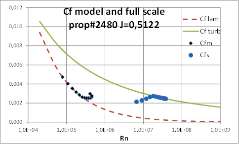
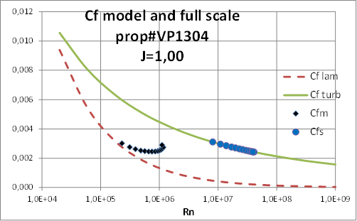
As an example, in fig. 4, values of CFm and CFs corresponding to the cylindrical sections of a case have been represented, at model scale and full scale, and including reference friction lines used in this procedure.
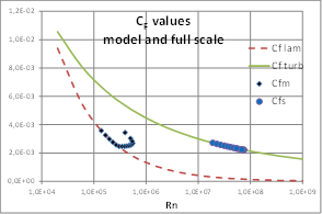 Figure 4: Values of CF for laminar, transitional and turbulent regime of flow of each blade section. Figure 4: Values of CF for laminar, transitional and turbulent regime of flow of each blade section. |
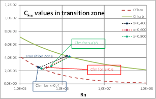 Figure 5: Values of CFm for some blade sections. Figure 5: Values of CFm for some blade sections. |
In fig. 5 a detail of three values of CFm of the same case are displayed. Value corresponding to x=0,4 is in laminar zone whilst values corresponding to x=0,6 and x=0,8 are in transition zone.
- VALIDATION OF NEW METHOD.
This new procedure has been validated by analyzing a comprehensive set of OWT results, both for conventional and end plate tip loaded (CLT) propellers available to authors. Two criteria have been established to validate it:
Criterion for conventional propellers: corrections obtained with present method for conventional propellers have to match reasonably the values obtained with ITTC’78-PPM within a small tolerance;
Criterion for unconventional propellers: corrections obtained with present method for unconventional propellers must produce full scale predictions in accordance with sea trials results. A complete set of data with model tests results and sea trials measurements are needed for each case and unfortunately only CLT propellers cases are available to authors.
3.1. Application to conventional propellers.
A comprehensive set of calculations with conventional propellers, covering a wide range of number of blades, area and pitch ratios, have been carried out in order to show that this method generates in “normal” cases practically same values of corrections as ITTC’78-PPM. There are some marginal cases, like propellers of small D (at model or at full scale) or OWT carried out at low rps, where calculations can differ somehow; but for these marginal cases it must be noticed that ITTC’78-PPM can give also unexpected results, for instance that η0S can be lower than η0m.
Criteria used for selection of propeller models have been:
4, 5 and 6 blades
Model diameter larger than 175mm
Different area ratios and pitch ratios covering maximum range as possible
Next tables show main characteristics of propellers selected for this exercise taken mainly from data base of CEHIPAR.
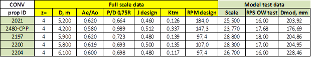
Table 2: CONVENTIONAL propeller models used for validation, z=4.
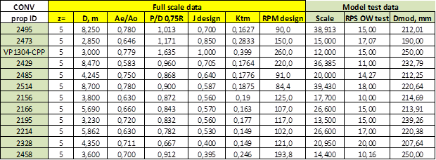
Table 3: CONVENTIONAL propeller models used for validation, z=5.
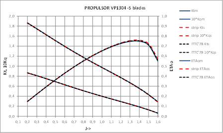
Among the subset of propellers with 5 blades it has been included propeller VP1304 that is the design selected by propulsion committee of the 27th ITTC to initiate a benchmark test for CFD (Computational Fluid Dynamics) calculations to investigate the capabilities of CFD to predict scale effects on the propeller performance. This work is continued during 28th ITTC.
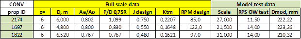
Table 4: CONVENTIONAL propeller models used for validation, z=6.
The ranges of main characteristics of conventional propellers used for validation are represented in next figures:
Pitch and area ratios in Fig. 6.
Model diameter and OW test rps in Fig. 7.
Values of Jdesign and corresponding Ktm in Fig. 8.
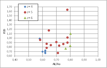
Figure 6: Set of conventional propellers used for validation. Pitch and area ratios.
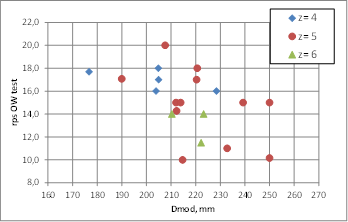
Figure 7: Set of conventional propellers used for validation. Model diameter and OW test rps.
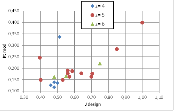
Figure 8: Set of conventional propellers used for validation. Values of J design and corresponding Ktm of each conventional propeller used in validation.
It can be appreciated in these figures that the propeller models used for this validation exercise are well distributed over a full range of main characteristics values so we can expect that most of conventional propellers will be within these ranges. There are 4, 5 and 6 bladed propellers and some of them are CPP type propellers, which demonstrate that the possibility of application of this strip method to any conventional type propeller is very high.
To compare calculations using this new strip method with results of ITTC’78-PPM next ratios have been calculated:
![]()
![]()
![]()
The dispersion of these ratios is presented in figure 9:
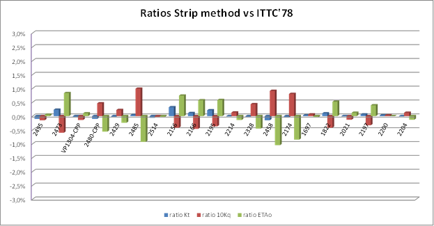
Figure 9: Distribution of comparison ratios used for validation in the case of CONVENTIONAL propellers.
It can be seen that ratios are within ±1.0% of results obtained using ITTC’78-PPM. In fact, most of them are within ±0.5% meaning that both methods are almost equivalent when applied to conventional propeller. In the cases where these ratios are larger (always within ±1.0%) the differences can be explained in view of the special geometry of the corresponding propellers, so we consider these differences as an improvement of this strip method.
Data and detailed calculations for some of these conventional propellers are presented in Appendix A. These detailed calculations show some relevant results:
1.- It is common that, due to the standard conditions of Open Water tests, section blades are operating in laminar or transition flow and that the formulation established in this paper gives a good approximation to the results obtained until now with the well proven ITTC’78-PPM procedure, but allowing to distinguish the influence of different blade geometries in OW corrections. At full scale and depending of propeller characteristics and operating conditions in some cases appear that also some section blades near to hub are operating in a transitional flow.
2.- KTs values are very close to that obtained by ITTC’78-PPM but 10KQs values differs a little bit more which can be explained because the influence of δ(CD) is larger in ΔKQ than in ΔKT; and because this new strip method computes viscous effects, which are main responsible for OW corrections, section by section instead of globally; so the small recorded differences are considered adequate and as an improvement over ITTC’78-PPM. These small differences will have small effects in the performance predictions of the propeller at full scale.
3.- In general it can be said that for conventional propellers present procedure can be comparable or almost equivalent to ITTC’78-PPM, being present strip method abler to establish small differences between different geometries of propellers with similar design conditions.
3.2. Application to unconventional propellers.
Main thesis of this study is that ITTC’78-PPM is not applicable to unconventional tip shape propellers; therefore, validation of this new strip method must be done correlating predictions obtained by applying this method with sea trials results. To obtain predictions from model tests it is necessary that a full set of model tests data will be available and unfortunately authors only have data of their own projects with CLT propellers to perform this correlation. Authors do not know detailed published data of tests of other unconventional propellers but we expect that other interested designers will apply this method to their own projects and publish the corresponding results that hopefully will confirm the validity of this procedure.
In appendix B two cases have been studied and presented in detail. Both cases have been published in references (10) and (11) including ship-owners as authors.
First case is a series of four sister ships LEG carriers of 12000 cbm delivered in a reduced space of time (10). Detail data presented in appendix B1 include ship and propeller main particulars, resistance, Open Water and self-propulsion tests model faired raw data and sea trials results of four ships. Extrapolations have been carried out by both procedures present strip method and ITTC’78-PPM, and these correlation calculations show that present strip method gives very accurate predictions.
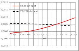
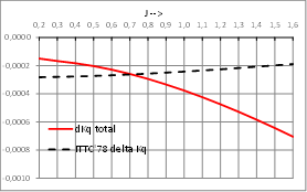
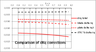
Second case is a twin shafts Ferry which data have been published in reference [11] and this propeller have also been used in several Research Projects funded by EU, LEADING-EDGE, SILENTV and AQUO. Only OW extrapolation data are presented but including the share of blade and end plate in the total effects ΔKt and ΔKq.
Comparison of the values of OWT corrections calculated by present strip method and ITTC’78-PPM both for conventional and for end plate propellers gives the explanation on how this strip method can give similar results to ITTC’78-PPM for conventional propellers and larger corrections in the case of unconventional tip loaded propellers. Physical interpretations of these results are coherent because viscous effects of end plate, in which are based the application of corrections to OWT, are less but of similar order of magnitude than effects of blade itself and must be added. ITTC’78-PPM cannot take these effects into account while present strip method does it.
- Conclusions
The main conclusions of the present study are as follows:
Confirmation that ITTC’78-PPM is not useful to predict propulsion characteristics of unconventional tip shape propellers based in model tests results.
Present method, going a step deeper in the basic principles of viscous effects:
1.- Is easy to implement in any prediction method based in model tests results like ITTC’78-PPM or similar methods used by towing tanks and other institutions.
2.- Computes with reasonable accuracy corrections to be applied to OWT to predict propulsion characteristics of conventional and unconventional propellers, mono-block or CPP type.
3.- Has a repetitive character, so same result values will be obtained for different users with the same input data. This is not the case when using CFD codes because of complication of the codes and differences among users.
According to all that, authors believed that strip method presented in this paper can be a candidate to be used as a recommended procedure to calculate OWT corrections for any type of propellers being an improvement over ITTC’78-PPM.
It would be encouraging if other institutions having more data of different ships and propeller types could use this method checking and communicating their results.
In particular authors expected that ITTC next conference will take into account this new procedure and could confirm that it is a possibility that can be used for unconventional tip shaped propellers.
NOMENCLATURE
| c, cx | section chord | (m) |
| t | section thickness | (m) |
| R | propeller radius | (m) |
| D | propeller diameter | (m) |
| r | section radius | (m) |
| x | non-dimensional section radius= r/R | (–) |
| s | non-dimensional arc length of the curved rake | (-) |
| z | number of blades | (–) |
| KT | Open Water thrust coefficient | (–) |
| KQ, 10KQ | Open water torque coefficient | (–) |
| ηo | Open water propeller efficiency | (–) |
| J | Open water advance coefficient | (–) |
| P/D, H/D | Pitch-diameter ratio | (–) |
| AE/Ao | Blade area ratio | (–) |
| CF, Cf | Friction coefficient | (–) |
| CD | Viscous coefficient | (–) |
| Rn, Rnco | Reynolds Number | (–) |
| kp | Average roughness of a plate | (m) |
| ν | kinematic viscosity of water | (m2/s) |
| ITTC | International Towing Tank Conference | |
| OWT | Open Water Test |
References
- ITTC [International Towing Tank Conference], 1978 Performance Prediction Method. ITTC-Recommended Procedures and Guidelines 7.5-02-03-01.4. Revised 2011.
- 27th ITTC-Copenhagen, 2014, vol. 2, pp 616.
- 14th ITTC, Report of the Performance Committee, 1975.
- Pėrez-Sobrino, M., et al. Scale effects in model tests with CLT propellers. 27th Motorship Marine Propulsion Conference, 2005.
- Bugalski, T. et al. Critical review of propeller performance scaling methods, based on model experiments and numerical calculations. POLISH MARITIME RESEARCH nº 4(80), 2013 Volume 20, 71-79.
- Von Doenhoff, A. E. et al. A Low-Speed Experimental Investigation of the Effect of a Sandpaper Type of Roughness on Boundary-Layer Transition. NACA Report 1349, August 1956.
- Brown, M. et al, Improving Propeller Efficiency Through Tip Loading. 30th Symposium of Naval Hydrodynamics, Hobart, Tasmania, Australia, 2-7 November 2014.
- Sánchez-Caja, A. et al., Scale effects on tip loaded propeller performance using a RANSE solver. Ocean Engineering, 2014.
- Prandtl-Tietjens, Applied Hydro- and Aeromechanics. DOVER Publications, Inc.
- González-Adalid, J. et al. Propulsion Optimization of a Series of Liquified Ethane Gas Carriers Including CLT Propellers. 38th Motorship Propulsion & Emissions Conference, Hamburg, Germany, pp. 11-12, May 2016.
- González-Adalid, J. et al. Comparison of Different Scaling Methods for Model Tests with CLT Propellers. 11th International Conference on Hydrodynamics [ICHD], October 2014, Singapore.
APPENDIX A- Detailed calculations for Conventional propellers
Some cases of the propeller listed in tables 2, 3 and 4 will be presented in detail in this appendix.
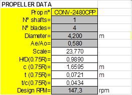
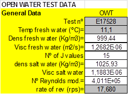
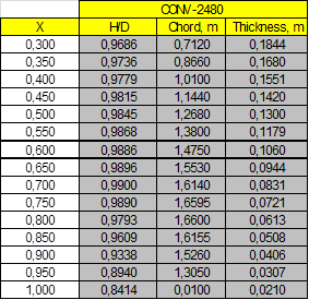
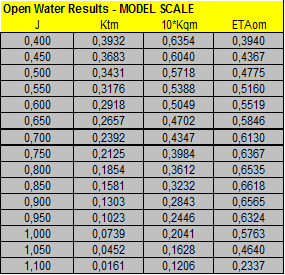
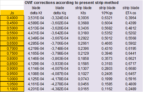
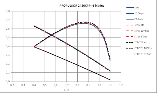
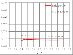
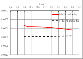
Case study A1- Propeller CEHIPAR-2480, CP Propeller type. 4 blades.
Propeller and Open Water tests data and calculations of ITTC’78 Open Water corrections:
 |
 |
 |
 |
 |
|
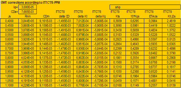
Calculation of Open Water corrections by present Strip Method:
 |
 |
  |
Detailed analysis of values of CF and CD of section profiles at model and full scale, at design J=0.5122:
 |
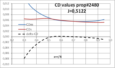 |
This case shows that developed strip method applied to a conventional CP propeller gives similar final results than ITTC’78-PPM. According to the strip method there appear that some sections of propeller model blades are operating in laminar flow and others in transition zone; but at full scale there are also some sections operating in transition flow conditions.
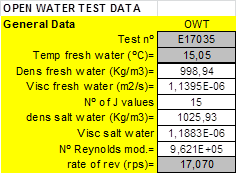
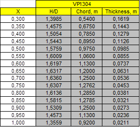
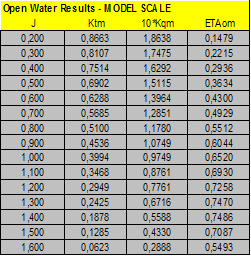
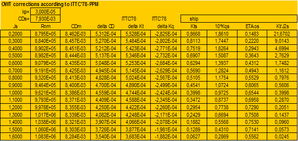
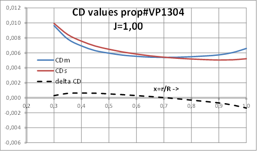
Case study A2- 28th ITTC benchmark CP propeller VP1304. 5 blades.
Propeller and Open Water tests data and Calculations of ITTC’78 Open Water corrections:
 |
 |
 |
 |
 |
|
Calculation of Open Water corrections by present Strip Method:
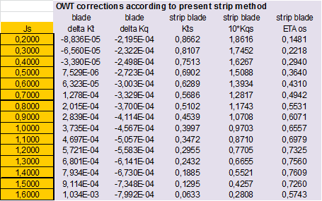 |
 |
  |
Detailed analysis of values of CF and CD of section profiles at model and full scale, at J=1.00:
 |
 |
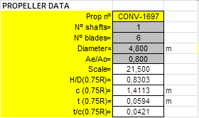
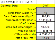
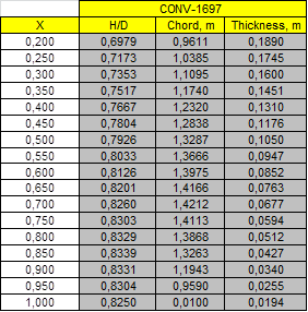
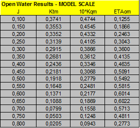
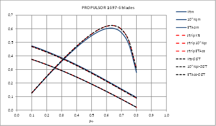
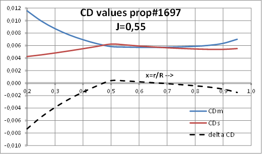
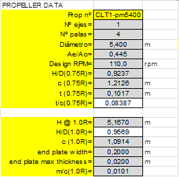
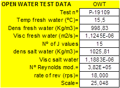
Case study A3- Propeller CEHIPAR-1697, FP Propeller. 6 blades.
Propeller and Open Water tests data and Calculations of ITTC’78 Open Water corrections:
 |
 |
 |
 |
 |
|
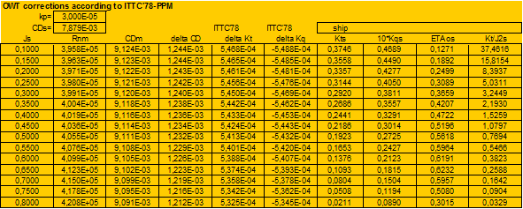
Calculation of Open Water corrections by present Strip Method:
 |
 |
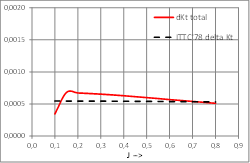 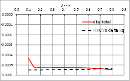 |
Other case of conventional propeller where OWT corrections calculated by present strip method and ITTC’78-PPM present a very good agreement.
Detailed analysis of values of CF and CD of section profiles at model and full scale, at J=0.7022:
 |
 |
APPENDIX B- Detailed calculations for Unconventional CLT propellers
Case study B1- LEG Carrier 12k cbm. This case is to be published in the 38th Motorship Propulsion & Emissions Conference to be held in Hamburg, 11-12 May 2016 (10).
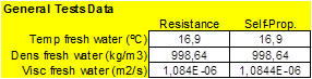
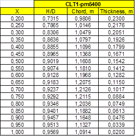
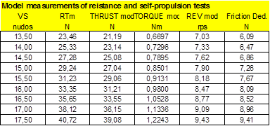
Propeller and model tests faired raw data are:
 |
  |
 |
 |
  |
|
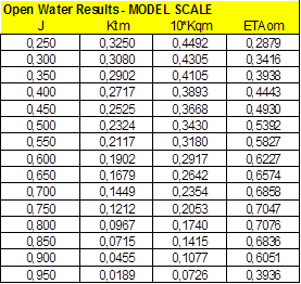
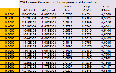
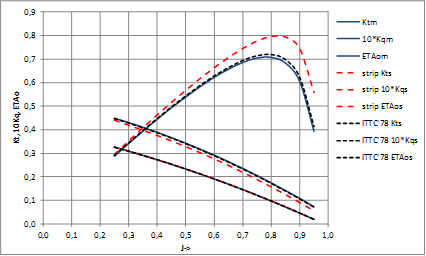
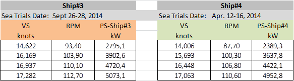
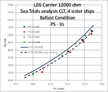
Analysis of OWT extrapolation (ITTC’78-PPM vs. present strip method):
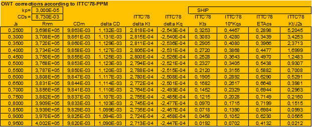 |
 |
 |
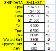
Sea Trials data and correlation with predictions computed using ITTC’78-PPM and using present strip method. In this case four sister ships were built of which sea trials data in ballast condition are available:
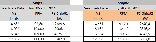 |
|
 |
|
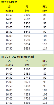 |
 It is clear that using OWT corrections calculated according to present strip method the predictions at full scale match sea trials results much better than using OWT corrections according to ITTC’78-PPM. It is clear that using OWT corrections calculated according to present strip method the predictions at full scale match sea trials results much better than using OWT corrections according to ITTC’78-PPM. |
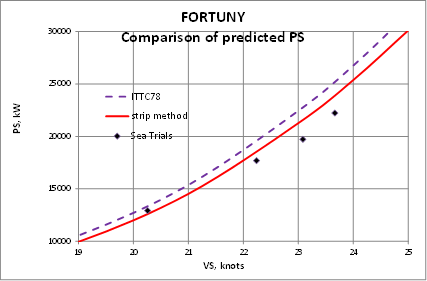
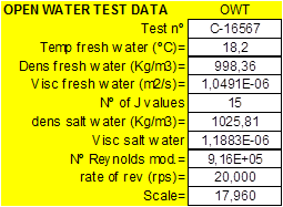
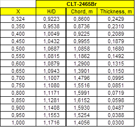
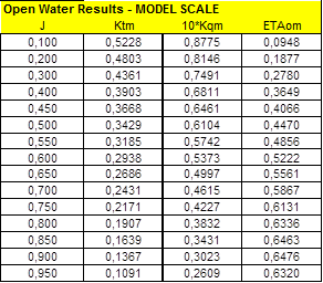
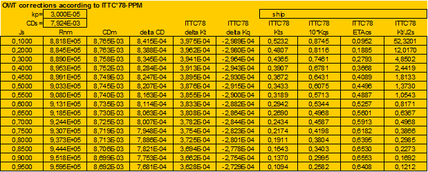
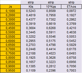
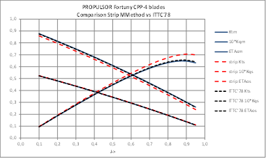
Case study B2- Twin shafts Ferry “FORTUNY”.
This case has been published in the 11th ICHD 2014, October 2014, Singapore, (11). It is a large Ferry propelled by two CPP propellers. In this reference detailed data of ship and propellers are given.
Propeller and OW test faired raw data are:
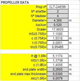 |
 |
 |
 |
As all data can be found in (11), in this appendix only detailed calculations of OWT corrections will be presented to compare present strip method and ITTC’78-PPM.
Analysis of OWT extrapolation (ITTC’78-PPM vs. present strip method):
 |
 |
 |
It has to be noticed that corrections due to end plate are an important part of total corrections as it is represented in next figures:
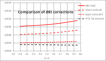 |
 |
Applying these corrections predictions at full scale are much more in line with sea trials measurements: